Metal Matrix Composites by Pressure Infiltrated Casting™
|
MatWeb Featured Article
By Matt Napier
PCC-AFT Composites
|
|
Casting of Metal Matrix Composites
Advances in Pressure Infiltrated Casting (PIC™) have allowed this process to meet the
challenges of delivering products with tight tolerances, high thermal conductivity, tailored coefficient of
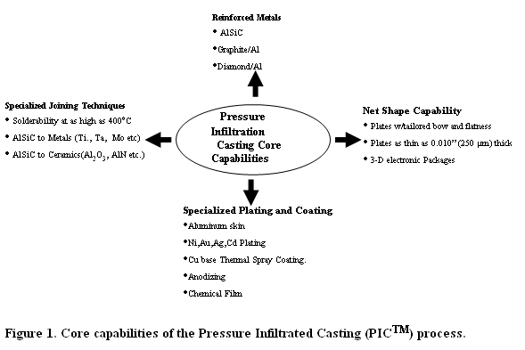
expansion, reduced weight and high stiffness. Current core capabilities are schematically illustrated in Figure 1.
They include net-shape metal reinforced components, mainly AlSiC (silicon carbide aluminum). Other materials, such as
graphite reinforced aluminum and diamond reinforced aluminum, used in applications where very high heat dissipation
is required, have recently been developed.
Net Shape Casting
Net-shape thin plate casting ability is one of the fundamental advantages of the PIC™ manufacturing process.
AlSiC Base plates 0.010”-0.2” thick and as large as 11”x7” have been in production. Net-shape parts are produced
by infiltrating preforms which contain all the details of the finished part within a casting mold system.
The casting molds are designed not only to contain the preforms, but to form the desired thickness of aluminum
skin and all the dimensions of the final part. As-cast parts can easily meet +/- 0.003” in length and width.
Figure 2 shows an example of a DBA (Direct Bond Aluminum)- AlSiC hyrbrid structure with an integrated heat
sink, carrier baseplate, ceramic substrate, and circuit pattern. The part has void-free in situ bonds, created
during a single pressure infiltrated casting operation.
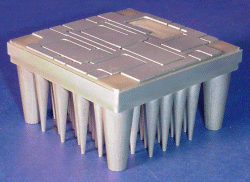
Figure 2. DBA-ALSiC hybrid structure with cast-in heat sink and circuit pattern
Plating and Coating
Metal skin on the finished product is characteristic of the PIC™ process. The pure metal skin allows
the part to be plated or finished as though it were an aluminum metal part. Cast parts fabricated using
the PIC™ process can be plated using traditional aluminum plating techniques and coated with various specialized
coatings. Ni and Ni/Au plating are utilized when AlSiC parts are soldered to other electronic components.
Cu base thermal spray coatings are also suitable for specific solder alloys. Chemical film coatings are
suitable for epoxy bonding. Since the coatings cost less than the Ni plating, these coatings easily
replace Ni plating in applications where the parts will be exposed to mildly corrosive environments.
Skinless parts can also be produced with PIC™.
In Situ Bonding
Another advantage of the PIC™ process is the ability to bond a variety of formerly unbondable materials.
Titanium, iron-based alloys, and ceramics have all been joined to AlSiC in situ using the PIC process.
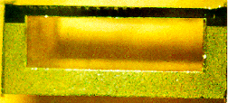
Figure 3 shows a hermetically sealed AlSiC electronic package with a Ti seal ring that was bonded in
situ during the PIC™ process.
An optical micrograph from a polished section of an in-situ formed AlSiC/Ti seal ring interface and welded
Ti lid/Ti seal ring interface are shown in Figure 3. The aluminum alloy in the joint is similar in chemical
composition to the AlSiC matrix and the aluminum skin covering the composite. There is no discontinuity such
as cracks or porosity at the aluminum/AlSiC interface and the aluminum/Ti interface.
 |
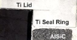 |
| Figure 3. Laser sealed AlSiC package, (left) and an optical micrograph illustrating an AlSiC-Titanium joint and a Ti lid/Ti seal ring weld. |
Due to the matched CTE of AlSiC and titanium, a Ti seal ring can be joined to AlSiC composites with minimal
post-fabrication stress. A Ti lid can then be welded to the Ti seal ring utilizing laser welding. Due to the
high thermal conductivity of AlSiC, the interface temperature remains below the melting temperature of aluminum
alloy during laser welding process. As a result, there is no change expected in this interface during the
welding process. Laser sealed AlSiC packages produced with Ti seal rings maintain the hermetic integrity after
1,100 thermal cycles between -55 and 125ºC.
Design Possibilities
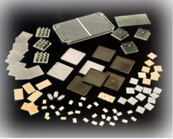
The variety of products in Figure 4 show the design flexibility provided by the PIC™ process.
Table 1 provides some general guidelines for engineers and designers. Pressure-Infiltrated Casting by
PCC-AFT Composites gives engineers the freedom to explore new opportunities in the design of thermal management solutions.
 |
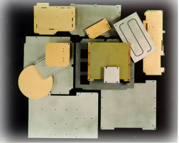 |
| Figure 4. Examples of the myriad of products already being produced with PCC-AFT Composites Group’s Pressure Infiltrated Casting process. |
Table 1: PCC/AFT Composites General Casting Design Guidelines
- Minimum thickness of plates: 0.010”.
- Draft on “vertical” features:
- 2º up to ¼” height.
- 3º up to ½” height.
- 5º over ½” height
- Minimum spacing between vertical features: 0.060”.
- Minimum spacing between holes: 0.050”.
- Minimum distance from edge of hole to edge of part: 0.060”.
- Fillet Radius to be 0.010” minimum with 0.040” optimal.
- Surface finish on part: 63 microinches RMS or better.
- Tolerances on locations of features on the part will be ±0.5% typical. Tighter tolerances must be evaluated based on the overall design.
- “As cast” flatness on plates is a function of plate thickness and configuration. Best case is 0.0015” per inch TIR, but quantify during the specification process
- Average Aluminum Skin thickness: 0.003” to 0.008”.
- Overall general best practices for casting process apply.
Table 2: Properties of materials produced by PCC-AFT Composites Group’s Pressure Infiltrated Casting process.
|
|
|
|
|
|
|
|
|
| Material |
AlSiC-30 |
AlSiC-63 |
AlSiC-SD |
AlSiC-68 |
AlSiC-70 |
AlGrf |
AlGrp |
ALDIp |
| Physical Properties |
|
|
|
|
|
|
|
|
| CTE (20-30 oC) |
14 |
8 |
7.3 (X)
8.1 (Y) |
7.4 |
7 |
9.1 |
7.6 |
5.5 |
| Thermal Conductivity (W/moK) |
165 |
175 |
175 |
175 |
175 |
123 (X)
291 (Y)
132 (Z) |
228 (X)
281 (Y)
209 (Z) |
400 |
| Electrical Resistivity (10-6 ohm-cm) |
|
|
|
24 |
|
6.9 (X,Y) |
|
|
| Density (g/cc) |
2.81 |
3.01 |
3.02 |
3.03 |
3.04 |
2.53 |
2.1 |
3.26 |
| Melting Pt. (oC) |
557 to 596 |
557 to 613 |
557 to 613 |
557 to 613 |
557 to 613 |
557 to 613 |
|
557 to 613 |
| Mechanical Properties |
|
|
|
|
|
|
|
|
| Ultimate Tensile (MPa) |
449 |
253 |
249 |
207 |
205 |
|
|
|
| Hardness (Rockwell B) |
|
88 |
88 |
97 |
99 |
|
|
|
| Young's Modulus (GPa) |
110 |
220 |
246 |
223 |
230 |
|
|
|
| Fracture Toughness (MPa*m1/2) |
20 |
|
|
|
10.6 |
|
|
|
